

ALL ALUMINUM V8.
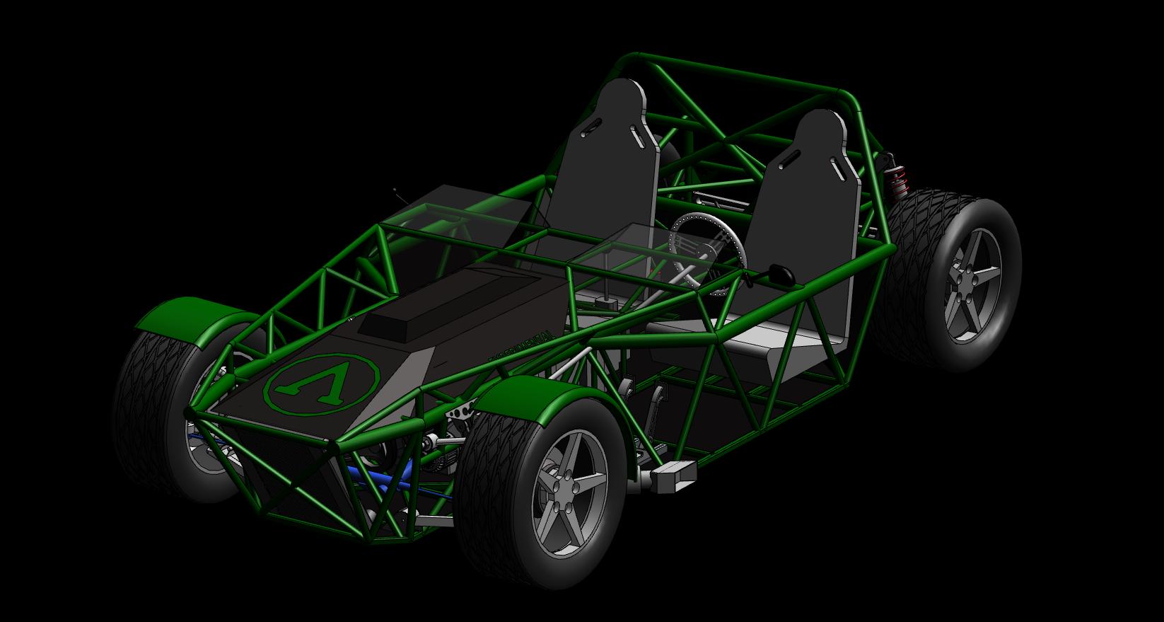
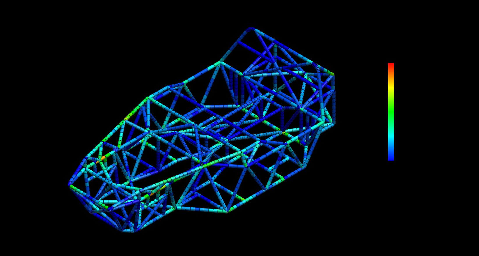
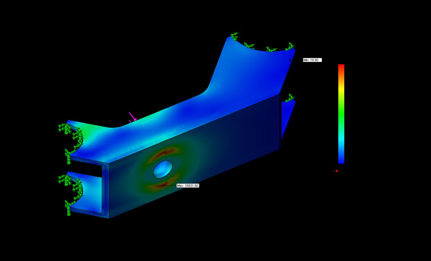
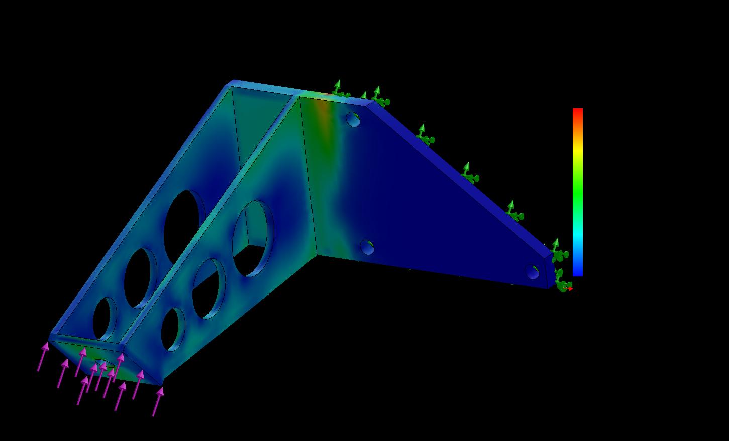
LIGHTWEIGHT SPACE FRAME CHASSIS.
SIX SPEED MANUAL GEARBOX.
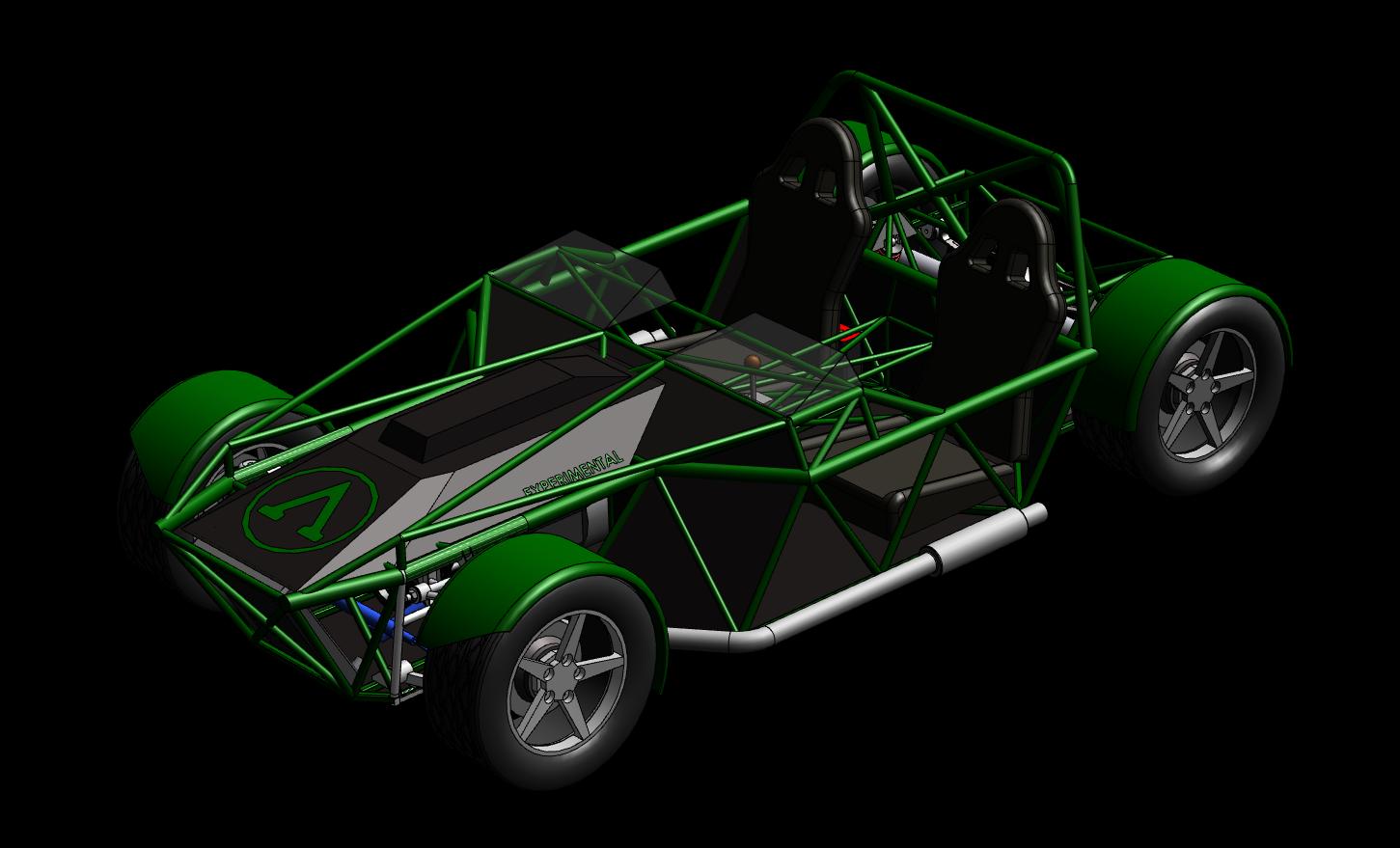
OPEN TOP ROADSTER.
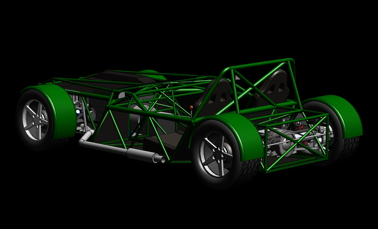
REAR WHEEL DRIVE.
EXOSKELETON DESIGN.
For Comparison:
Lamborghini Murcielago - 5.8 lbs/hp
Porsche 911 GT2 - 7.1 lbs/hp
Ariel Atom SC - 4.7 lbs/hp
Ferrari Enzo - 4.6 lbs/hp
Corvette C6 ZR1 (SC) - 5.24 lbs/hp
*Click the Updates link on the left to see the most recent developments.*
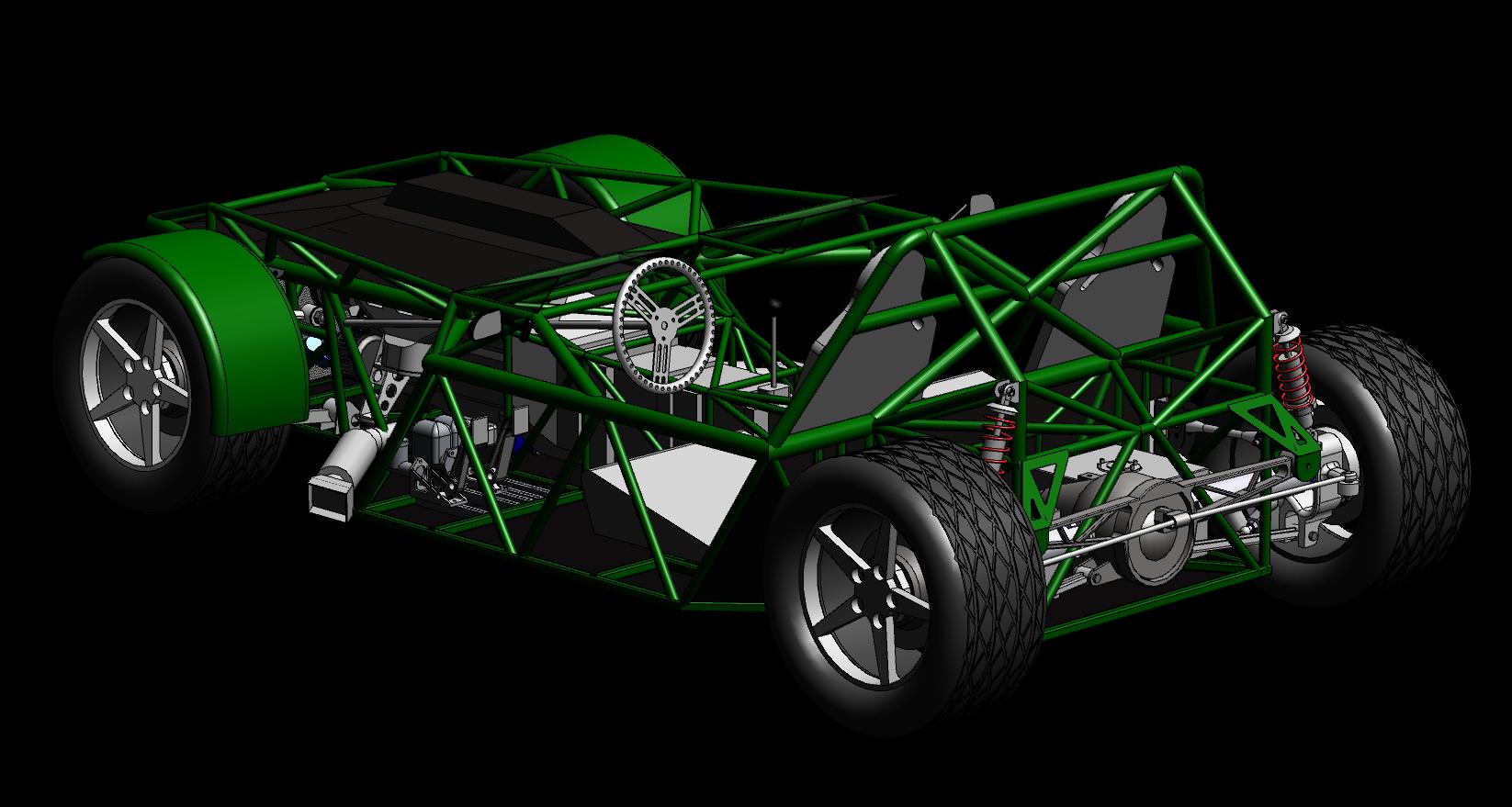
LIGHTWEIGHT SPACE FRAME CHASSIS.
SIX SPEED MANUAL GEARBOX.
OPEN TOP ROADSTER.
REAR WHEEL DRIVE.
EXOSKELETON DESIGN.
These elements come together in the Spartan V8, our take on the minimalist exoskeleton car. With a target curb weight of 1600 lbs and base horsepower of 350 hp, it boasts a power to weight ratio of 4.57 lbs/hp (!2.50 lbs/hp with top engine option!). Traction and aerodynamics aside, power to weight is the primary factor in determining acceleration. This makes it easy to compare basic acceleration between any cars with a known curb weight and power output.
For Comparison:
Lamborghini Murcielago - 5.8 lbs/hp
Porsche 911 GT2 - 7.1 lbs/hp
Ariel Atom SC - 4.7 lbs/hp
Ferrari Enzo - 4.6 lbs/hp
Corvette C6 ZR1 (SC) - 5.24 lbs/hp
The Spartan V8 immerses you in the motoring experience as only few other cars can. No electronic nannies correct your mistakes for you - no traction control, no anti-lock, no stability control. Just man and machine in perfect harmony, screaming through the curves as one. Purpose designed and built, but not strictly a track day car - for everyday use as well. The engine runs on regular gasoline and gets upwards of 20 mpg, the chassis can handle speed bumps and potholes, there is a luggage tray aft of the seats, and a small hitch receiver at the rear for adding a hitch cargo carrier for even more luggage room. The Spartan V8 is then not only a track day car or even a daily drivable car, but is also a touring car that could be driven cross country in relative comfort - provided it doesn't rain.
*Click the Updates link on the left to see the most recent developments.*
Take a look around, and feel free to leave a comment!
Favorite Suppliers:
http://www.fattyschassis.com

http://www.hrpworld.com/

http://www.southwestspeed.com
http://www.summitracing.com

http://www.ddperformance.com/index.php